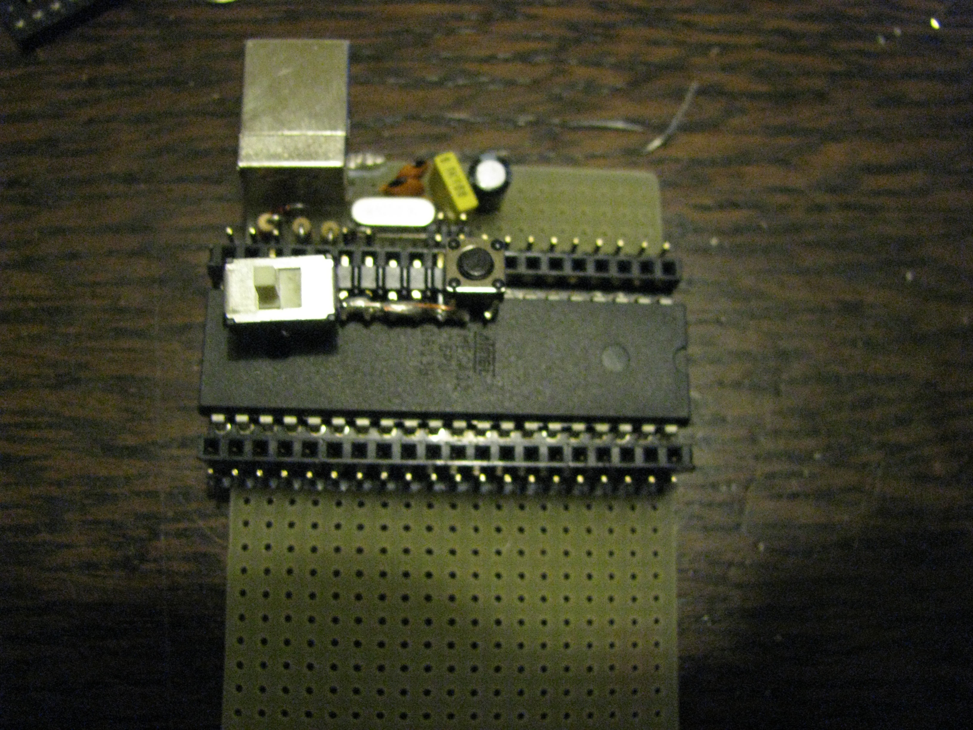
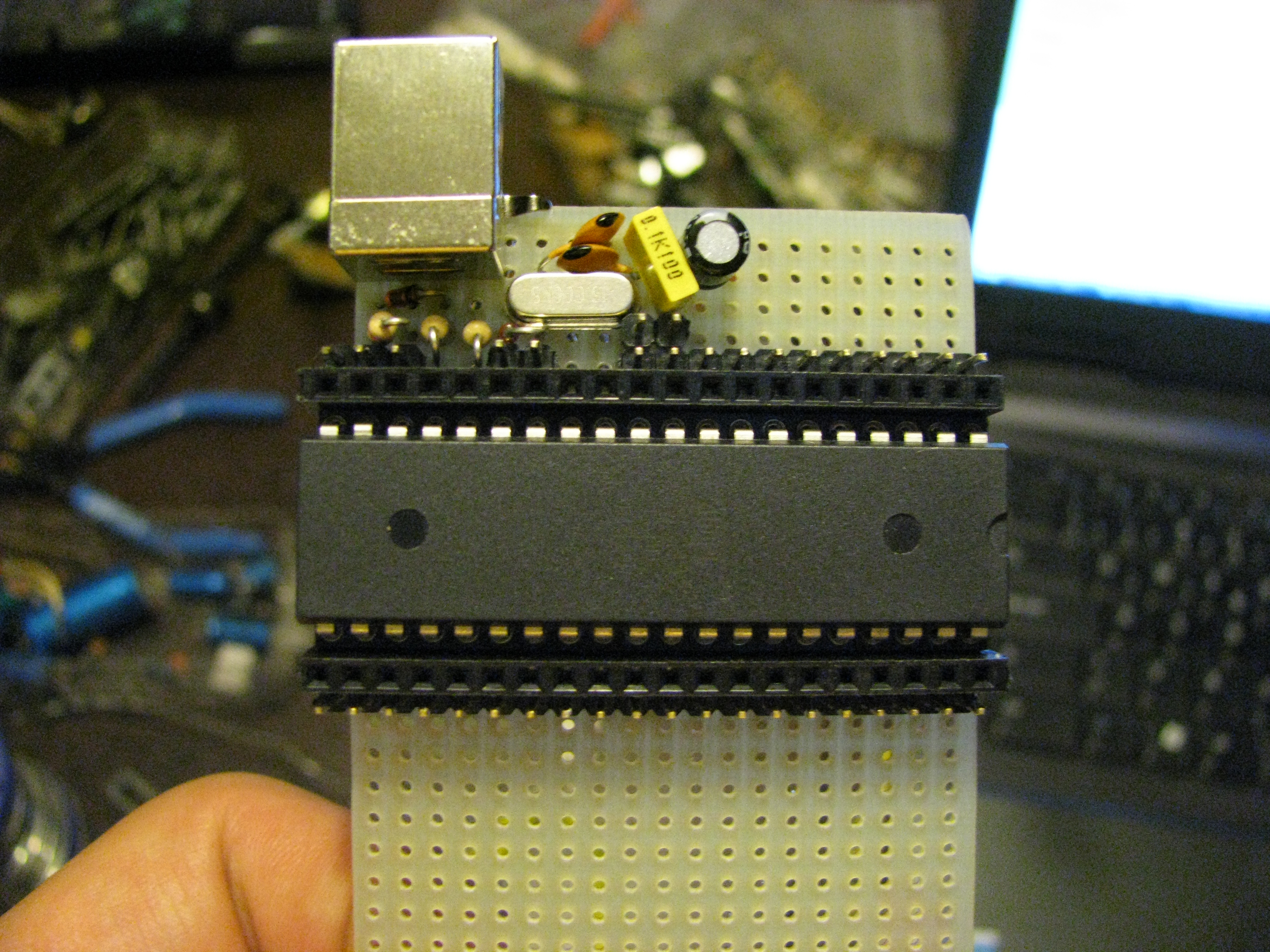
and here is the board:
This board was used to drive the display of a cheap Daft Punk helmet rip-off with a 16x6 LED display. Read on for the details.
This is a step-by-step tutorial on how to build a small, multi-purpose development board, based on an ATMega32 microcontroller. It is based on the Metaboard, but there is no etching involved and there are more pins available. The build took about 3h. I am not very skilled with a soldering iron and I had to take pictures along the way, which slowed me down considerably. This board was used to drive the display of a cheap Daft Punk helmet rip-off with a 16x6 LED display.
Bill of materials: * 1x board with through-holes, at least 19x15 holes. The one I used has 19x38 holes. * 1x USB B connector * 1x large 40-pin DIL socket * 2x 20-pin 1-row female header (or one 41+ pin header) * 1x 40-pin 1-row male header * 2x 68 ohm resistor * 1x 2.2K resistor * 1x 16MHz quartz * 2x22pF capacitor * 1x 100nF ceramic capacitor * 1x 20+microF capacitor * 2x 3.6, 500mA Zener diode * 1x ATMega32 MCU
First, the schematic. As you can see, it's really simple. Use it as a reference while building the board.
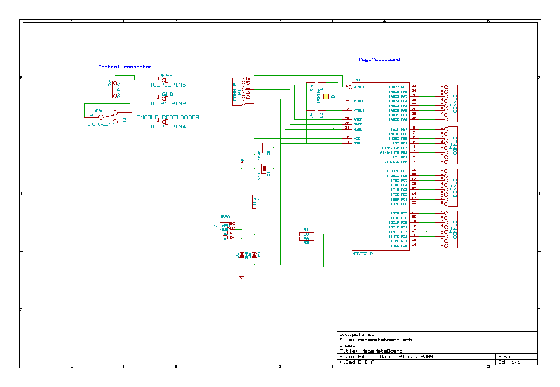
If you prefer, you can use the postscript version
The build:
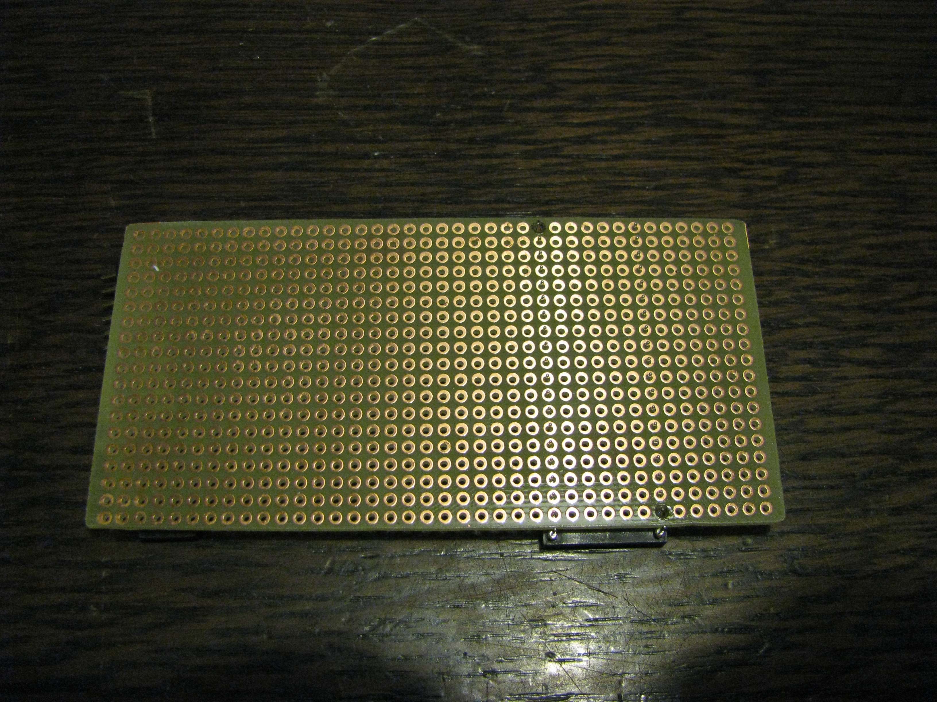
Start with the board

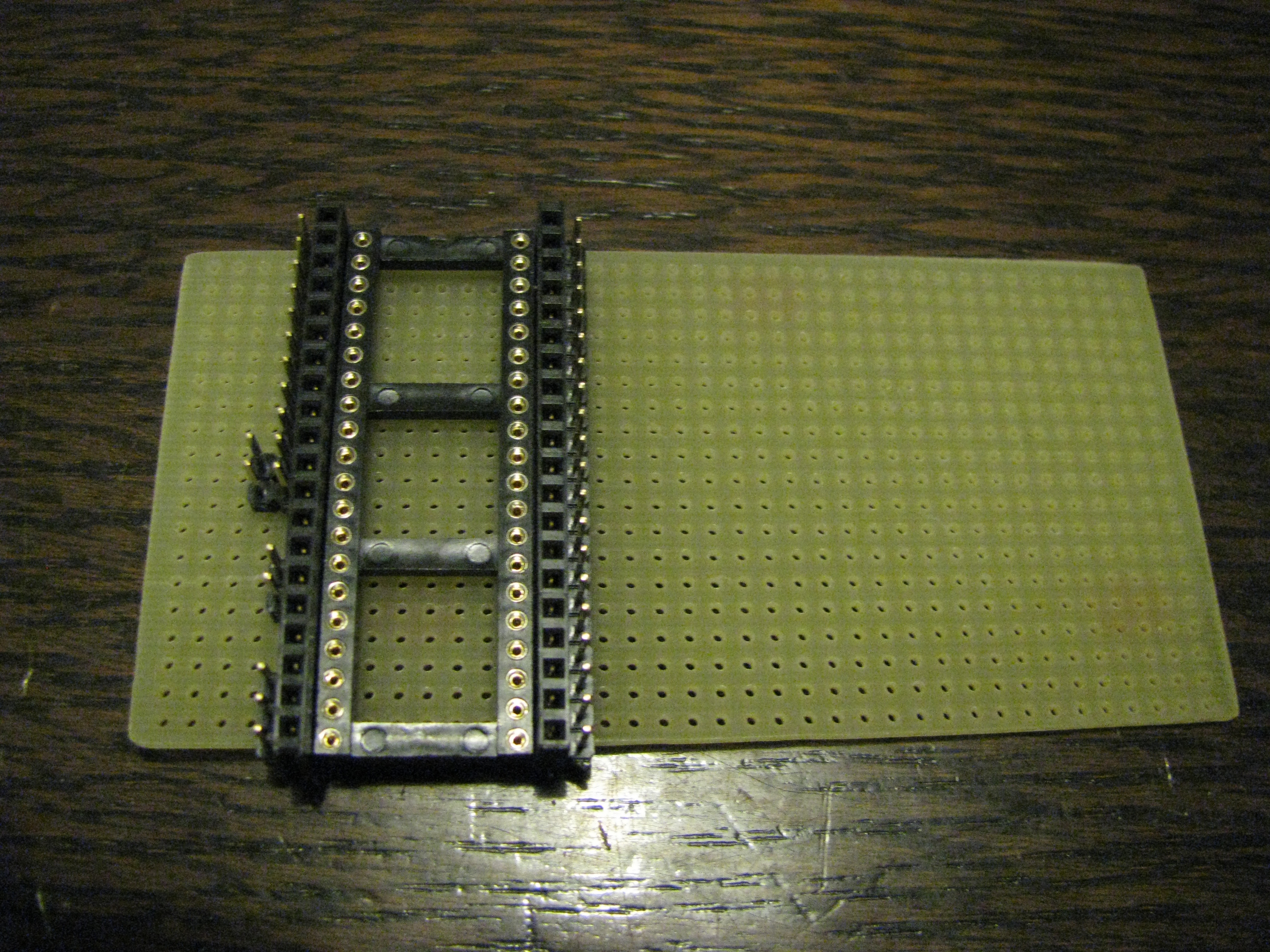
Place the socket 7 pins from the edge and solder it so it doesn't fall off.
Add the headers. Cut the male headers into 1x20-pin, 2x2-pin, 1x11-pin and 1x3-pin pieces. You can use one of the smaller pieces to prevent the board from tipping over while you're soldering.
Place the quartz, Q1 and 22pF capacitors, C3 and C4. Cross the leads which connect to the ground. Twist the leads of the quartz and capacitors as you can see in the picture. Be careful to keep the lead away from pin 14 of the MCU. Solder these 3 components.
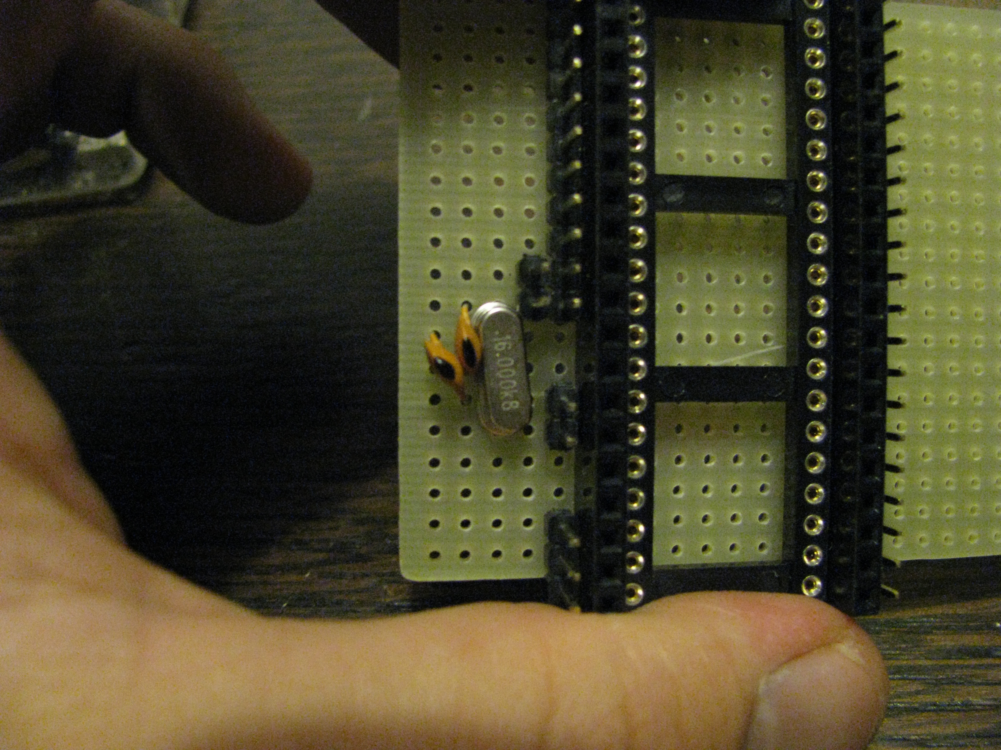](../../../galleries/megametaboard/build08-QC-soldered.jpg)
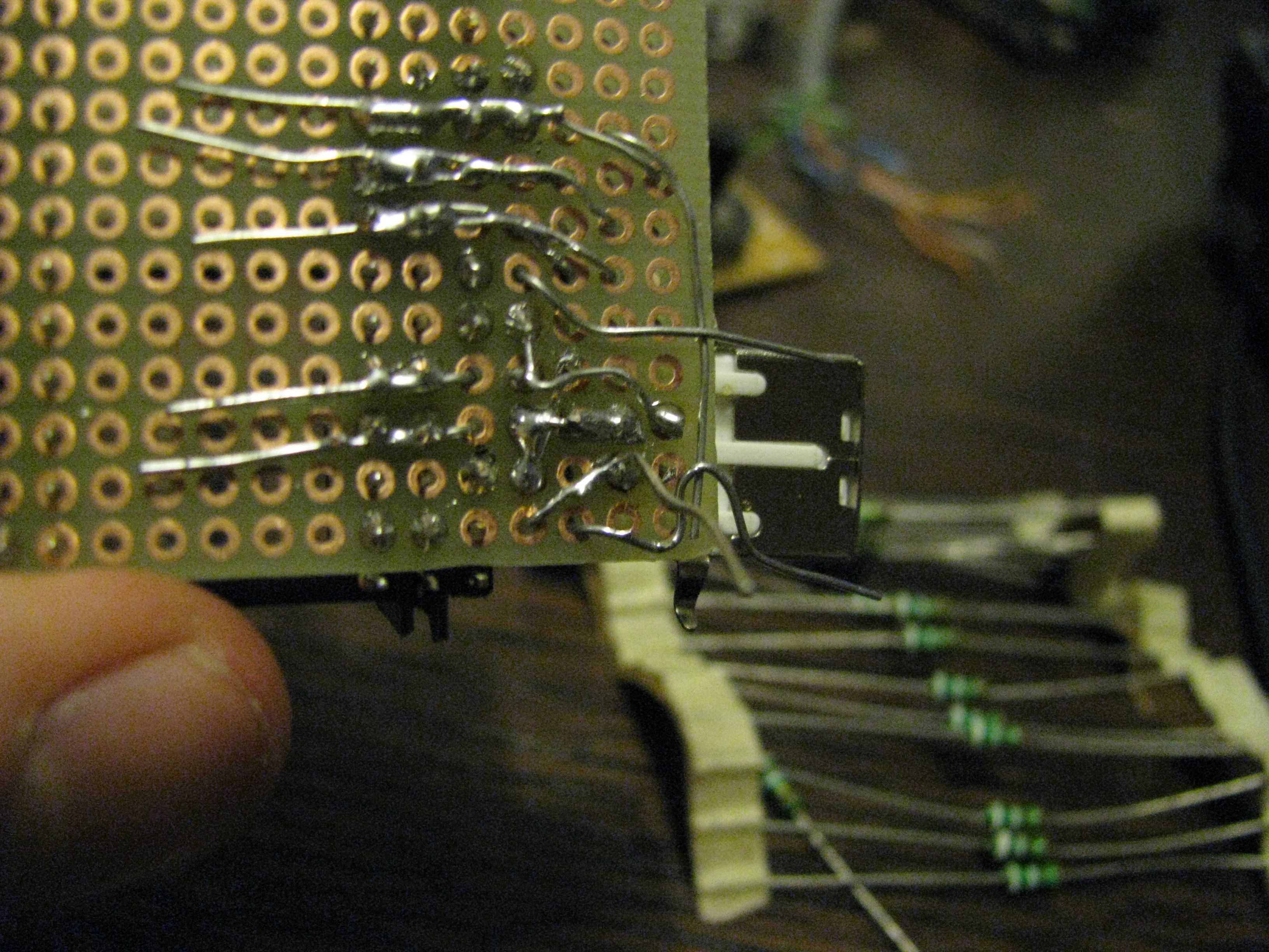
Place R1 and R2. Twist the two leads which connect to the MCU. Then place R3 and cross the leads of R1 and R3.
](../../../galleries/megametaboard/build11-R123-cross.jpg)
Solder the components and snip off the the excess part of the lead from R3 to R1.

Place the Zener diodes. Mind the polarity. Make sure the leads from D1 do not connect to pins 13, 14 or 15 of the MCU.

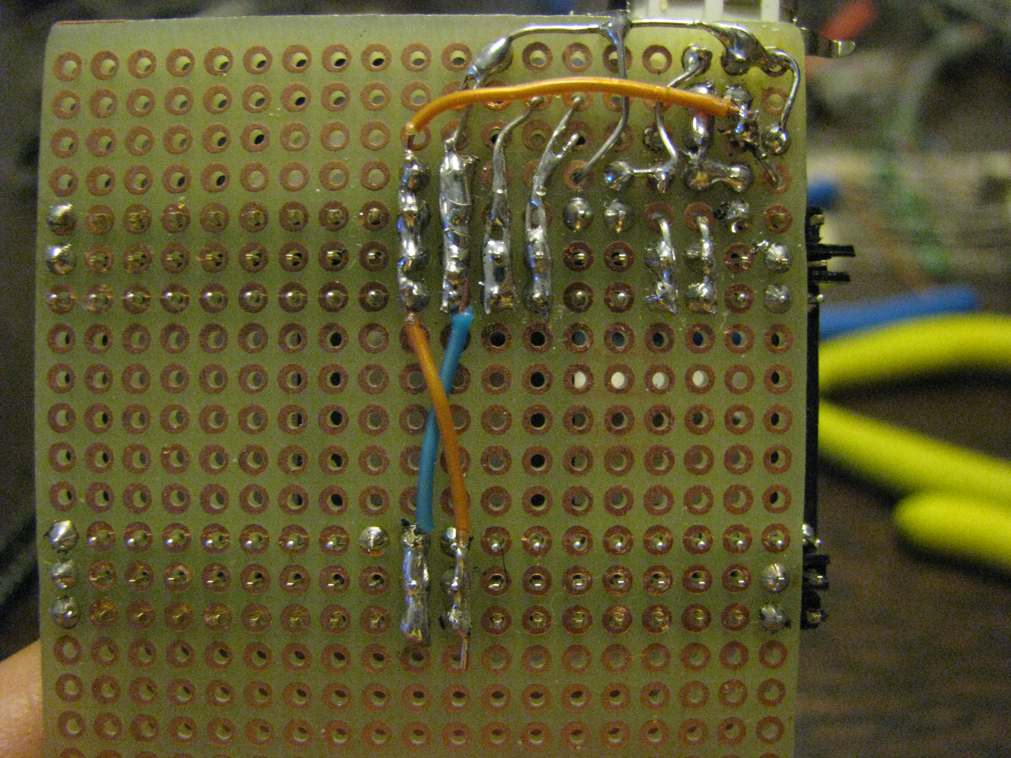
Place the USB connector. Connect the unused lead from R3 to the power pin on the USB connector by twisting it diagonally. Twist the leads from R1 and R2 so they connect to D+ and D- on the USB connector.
Twist the unused leads from D2, D1 and C4 to form a connection to GND. Solder them together.

Snip off the excess parts of the leads. Use one piece of wire to connect the two MCU ground pins - 11 and 32. Use two pieces of wire to connect pins 10 and 30 of the MCU to the +5V pin of the USB connector.
Use small pieces of wire to connect the MCU to the adjacent header pins.
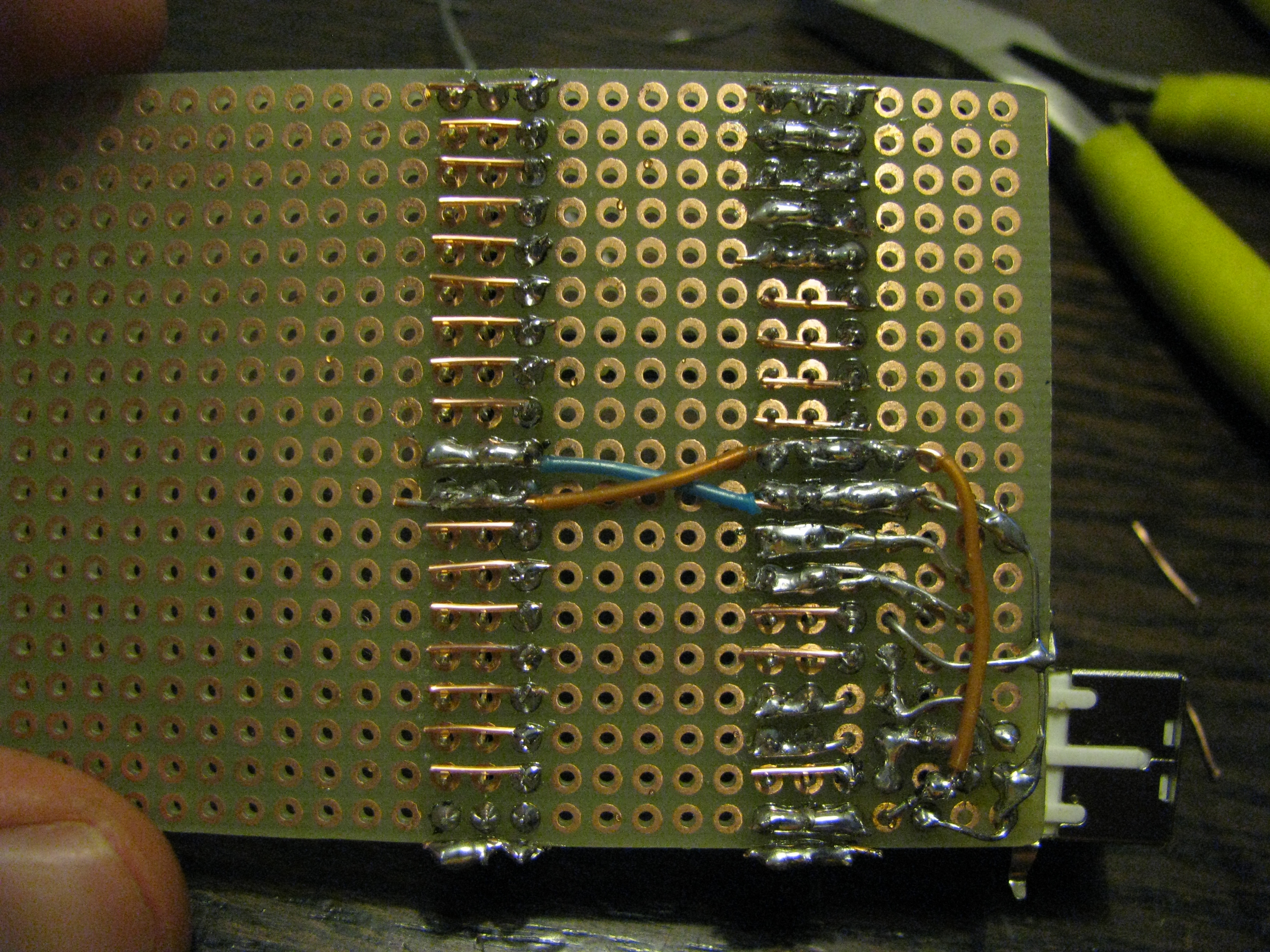
Add the two large capacitors- C1 and C2 and connect them across +5V and GND.

The MegaMetaBoard is now complete. However, you will still need some way to connect pin 18 (PD4) of the MCU to GND when programming the board. It's also a good idea to add a reset button.
One solution is to use a 10-pin, one row horizontal header. Snip off all but 3 pins - use a small pushbutton to connect RESET to GND using two pins and a small switch to connect PD4 to GND while programming. A switch is easier to set/reset than a jumper. You can, of course, use wire and place the button and switch on the board.

Upload the bootloader to your ATMega32 and place it in the socket. Use the buttons. Rejoice.